Arduino Line Follower Take Two
This post covers our second attempt at building a line follower, code in this post includes everything up to commit 6aff577e6572b87e08e7, things may change so refer to this particular commit for this project.
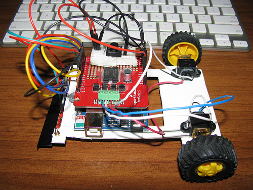
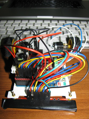
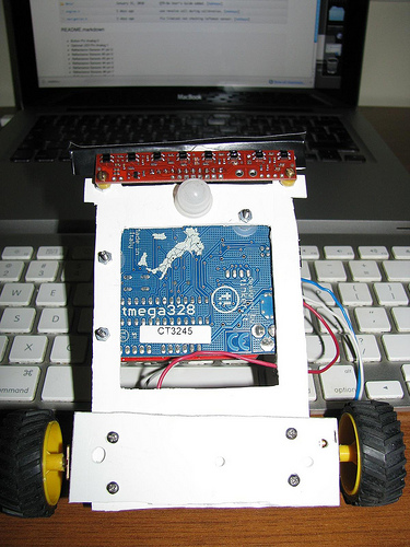
Stuff you will need,
- QTR-8RC Reflectance Sensor Array
- Ardumoto - Motor Driver Shield
- 2x Micro Metal Gearmotor 30:1
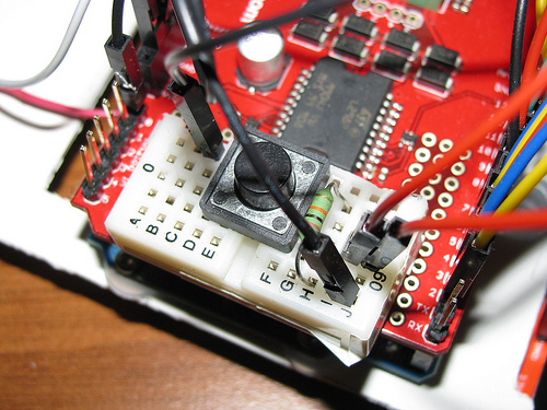
Pin arrangement for this particular project,
- Button Pin Analog Pin 0
- Optional LED Pin Analog Pin 1
- Reflectance Sensor #1 Digital Pin 2
- Reflectance Sensor #2 Digital Pin 3
- Reflectance Sensor #3 Digital Pin 4
- Reflectance Sensor #4 Digital Pin 5
- Reflectance Sensor #5 Digital Pin 6
- Reflectance Sensor #6 Digital Pin 7
- Reflectance Sensor #7 Digital Pin 8
- Reflectance Sensor #8 Digital Pin 9
Code for this project is divided into two modules, engine and navigation. Engine is responsible for all movement while navigation is responsible for tracking the line.
#define PwmPinMotorA 10
#define PwmPinMotorB 11
#define DirectionPinMotorA 12
#define DirectionPinMotorB 13


void engineSetup(){
  // motor pins must be outputs
  pinMode(PwmPinMotorA, OUTPUT);
  pinMode(PwmPinMotorB, OUTPUT);
  pinMode(DirectionPinMotorA, OUTPUT);
  pinMode(DirectionPinMotorB, OUTPUT);
}
Pins 10 through 13 is used by the Ardumoto shield, before we can interact with the motors we need to set these pins to OUTPUT mode.
void motor(int motor,int speed){
#ifdef POWER
  int pwmPin = 10;
  int dirPin = 12;
  int dir = HIGH;

  if(motor == MotorB){
    pwmPin = 11;
    dirPin = 13;
  }

  if(speed < 0){
    dir = LOW;
    speed = -1 * speed;
  }

  analogWrite(pwmPin, speed);
  digitalWrite(dirPin, dir);
#endif
}
We control the speed and direction of the motors using the motor function, it takes two variables the motor we want to control (MotorA or MotorB) and the speed we want to turn it at, an integer in the range -255 to 255, -255 being reverse full power and 255 being forward full power.
void revolve(int speed , int direction){
  if (direction == REVOLVE_LEFT ){
    motor(MotorA,speed);
    motor(MotorB,-speed);
  }else{
    motor(MotorA,-speed);
    motor(MotorB,speed);
  }
}
A helper function which is used during the calibration phase is the revolve function which makes the robot revolve around itself, so we don't have to move the robot by hand. It takes two parameters the speed we want it to revolve around and the direction of turn (either REVOLVE\LEFT or REVOLVE\RIGHT).
void calibrate(PololuQTRSensorsRC* qtr){
  revolve(CALIBRATION_SPEED,REVOLVE_LEFT);

  int i;
  for (i = 0; i < 125; i++){
    qtr->calibrate(QTR_EMITTERS_ON);
    delay(20);
  }

  revolve(0,REVOLVE_LEFT);
}
Before we ask the navigation module for line position, sensors needs to be calibrated. This is done by making the robot revolve around itself while calling calibrate which saves the maximum and minimum values read from sensors overtime internally. This will allow us to not only track white line on black surface or vice versa but also to track black line on a gray surface.
bool lineLost(unsigned int* vals){
  bool lost = true;

  if (TRACKING_WHITE == 0){
    for(int i=0;i<NUM_OF_SENSORS;i++){
      if (vals[i] > WHITE_TRASHOLD){
        lost =false;
      }
    }
  }else{
    for(int i=0;i<NUM_OF_SENSORS;i++){
      if (vals[i] < BLACK_TRASHOLD){
        lost =false;
      }
    }
  }
  return lost;
}
We need a couple of predicate functions to properly follow a line one of which is lineLost, given an array of sensor readings we have to determine if the line we are following is under the sensor array or not. This is done by checking if any of the sensors are reading black while following a black line or any of the sensors are reading white while following a white line.
void detectTrackColor(unsigned int* vals){
  if ((vals[0] < WHITE_TRASHOLD) &&
      (vals[NUM_OF_SENSORS - 1] < WHITE_TRASHOLD))
    TRACKING_WHITE = 0;

  if ((vals[0] > BLACK_TRASHOLD) &&
      (vals[NUM_OF_SENSORS - 1]> BLACK_TRASHOLD))
    TRACKING_WHITE = 1;
}
Track color is detected automatically with every read. This allows the robot to adapt to changing surface color. If leftmost and rightmost sensors both read black we assume surface is black so we set TRACKING\WHITE to true. If leftmost and rightmost sensors both read white we assume we are on a white surface tracking a black line so we set TRACKING\WHITE to false.
int checkEdge(unsigned int* vals){
  if (TRACKING_WHITE == 0){
    if ((vals[NUM_OF_SENSORS - 1] > WHITE_TRASHOLD) &&
        (vals[NUM_OF_SENSORS - 2] > WHITE_TRASHOLD) &&
        (vals[NUM_OF_SENSORS - 3] > WHITE_TRASHOLD) &&
        (vals[0] < WHITE_TRASHOLD) &&
        (vals[1] < WHITE_TRASHOLD) &&
        (vals[2] < WHITE_TRASHOLD)){
      return EDGE_LEFT;
    }
    if ((vals[0] > WHITE_TRASHOLD) &&
        (vals[1] > WHITE_TRASHOLD) &&
        (vals[2] > WHITE_TRASHOLD) &&
        (vals[NUM_OF_SENSORS - 1] < WHITE_TRASHOLD) &&
        (vals[NUM_OF_SENSORS - 2] < WHITE_TRASHOLD) &&
        (vals[NUM_OF_SENSORS - 3] < WHITE_TRASHOLD)){
      return EDGE_RIGHT;
    }
  }else{
    if ((vals[NUM_OF_SENSORS - 1] < BLACK_TRASHOLD) &&
        (vals[NUM_OF_SENSORS - 2] < BLACK_TRASHOLD) &&
        (vals[NUM_OF_SENSORS - 3] < BLACK_TRASHOLD) &&
        (vals[0] > BLACK_TRASHOLD) &&
        (vals[1] > BLACK_TRASHOLD) &&
        (vals[2] > BLACK_TRASHOLD)){
      return EDGE_LEFT;
    }
    if ((vals[0] < BLACK_TRASHOLD) &&
        (vals[1] < BLACK_TRASHOLD) &&
        (vals[2] < BLACK_TRASHOLD) &&
        (vals[NUM_OF_SENSORS - 1] > BLACK_TRASHOLD) &&
        (vals[NUM_OF_SENSORS - 2] > BLACK_TRASHOLD) &&
        (vals[NUM_OF_SENSORS - 3] > BLACK_TRASHOLD)){
      return EDGE_RIGHT;
    }
  }
  return 0;
}
checkEdge provides a way to detect 90 degree turns (edges) on a track. This works just like track color detection but instead of checking leftmost and rightmost sensor readings we check leftmost and rightmost sensors in groups of three, assuming we are tracking a white line, when we read the sensors on an edge at least three sensors will read white and three sensors will read black, if we detect a 90 degree turn we return EDGE\RIGHT or EDGE\LEFT depending on the turn or 0 indicating no edge, but unfortunately this makes the robot a little bit twitchy so depending on the track you can enable or disable this using config.h.
int readLine(PololuQTRSensorsRC* qtr){
  unsigned int val[NUM_OF_SENSORS];
  qtr->readCalibrated(val);

  detectTrackColor(val);

  int line = qtr->readLine(val,QTR_EMITTERS_ON,TRACKING_WHITE);

#ifdef DEBUG
  Serial.print(TRACKING_WHITE);   Serial.print(" ");
  Serial.print(line);   Serial.print(" R< ");
  Serial.print(val[0]); Serial.print(" ");
  Serial.print(val[1]); Serial.print(" ");
  Serial.print(val[2]); Serial.print(" ");
  Serial.print(val[3]); Serial.print(" ");
  Serial.print(val[4]); Serial.print(" ");
  Serial.print(val[5]); Serial.print(" ");
  Serial.print(val[6]); Serial.print(" ");
  Serial.print(val[7]); Serial.print(" >L ");

  if (lineLost(val) == true)
    Serial.print("Line Lost \n");
  if (checkEdge(val) != 0)
    Serial.print("Edge \n");
#endif

  if (lineLost(val) == true)
    return LINE_LOST;
#ifdef EDGED_TRACK
  else if (checkEdge(val) != 0)
    return checkEdge(val);
#endif
  else
    return line;
}
readLine is the only function we will call to get our position relative to the line, first it reads calibrated sensor values then we detect track color and call readLine which returns a value between 0 and ((number-of-sensors*1000) - 1000), in this robot with 8 sensors it will return numbers between 0 and 7000, 0 means line is under sensor 1, 1000 means line is under sensor 2 so on and so forth. This value is what we use for navigation unless we lost the line or we are on an edge.
Button button = Button(14,PULLDOWN);
const int ledPin = 15;
PololuQTRSensorsRC qtr((unsigned char[]) {2,3,4,5,6,7,8,9}, NUM_OF_SENSORS);
Arduino sketch starts by initializing button, pin and the reflectance sensors,
void setup(){
#ifdef DEBUG
  Serial.begin(9600);
#endif

  pinMode(ledPin, OUTPUT);
  engineSetup();

  while(button.isPressed() == false);
  calibrate(&qtr);
  while(button.isPressed() == false);

  delay(2000);

  motor(MotorA,FORWARD_MAX);
  motor(MotorB,FORWARD_MAX);
}
Next we setup the engine and the optional LED then we wait for a button press which will initiate sensor calibration, after we are done with calibration we wait for another button press and after two seconds robot will start moving.
void loop(){
  int pos = readLine(&qtr);

  if (pos != LINE_LOST){

    if (pos == EDGE_RIGHT){
      motor(MotorA,REVERSE_MAX);
      motor(MotorB,FORWARD_MAX);
    }else if (pos == EDGE_LEFT){
      motor(MotorA,FORWARD_MAX);
      motor(MotorB,REVERSE_MAX);
    }else{

      int error = pos - MIDDLE_POS;
      int m1Speed = FORWARD_MAX;
      int m2Speed = FORWARD_MAX;

      if (error < 0)
        m1Speed = map(error,-MIDDLE_POS,0,REVERSE_MAX,FORWARD_MAX);
      else
        m2Speed = map(error,0,MIDDLE_POS,FORWARD_MAX,REVERSE_MAX);

#ifdef DEBUG
      Serial.print(error);   Serial.print(" ");
      Serial.print(m1Speed); Serial.print(" "); Serial.println(m2Speed);
#endif

      motor(MotorA,m1Speed);
      motor(MotorB,m2Speed);
    }
  }
}
For navigation we constantly call readLine, its return value will be one of four things, it can be LINE\LOST in this case we would like to keep going in our previous direction no course corrections occurs, or it can be EDGE\RIGHT or EDGE\LEFT, if we are on a 90 degree turn in which case we turn the motors in reverse of each other which initiates a hard turn, finally it can return the actual line reading which is between 0 and 7000 for eight sensors we take this value, and calculate the error, we want to keep the line in the middle of the sensor array, so we subtract the return value of the readLine from our desired middle position, which will put the error value in the range -3500 and 3500 using this error value, we calculate new motor speeds that will decrease the error down to 0, we do this by mapping the error in the range 0 to middle position to range FORWARD\MAX to REVERSE\MAX (these are defined in config.h). We set the motor speeds to these freshly calculated motor speeds. These pretty much covers the meat of the code, following videos shows the robot in action.